
Best in Class Daylight for Color Critical Appraisals
byko-spectra pro - 7 illuminants
Product InfoLet there be light!
Uniform color is directly associated with high quality and influences our purchasing decision. This is especially true for multi-component products consisting of different materials and or being produced by different suppliers. The human eye is often the final judge for approving a new design. Therefore, the visual inspection conditions need to be standardized to guarantee repeatable visual results. The most important color match is under natural daylight. The CIE defined several standard D illuminants with D65 being the most important one. The lamps used in a light booth must simulate D65 as close as possible. Until now, fluorescent tubes were used to simulate D65. A new unique lighting setup is now able to achieve class A quality by simulating CIE D65 with a smart combination of filtered halogen lamps and LEDs.
Color perception is dependent on personal experience as well as illumination and surrounding observing conditions. As the ambient conditions are highly variable and not consistent at all, it is required to standardize common lighting situations. The illumination should be easily switchable in order to observe and avoid so-called “Metamerism”, i.e. differences in color matching when lighting conditions change. In order to guarantee reliable testing and evaluation conditions, international standards specify testing procedures defining the following components: [1] [2] [6] [7] [10] [12] [13]
The observer must have normal color vision and should be properly trained in evaluating colors. To avoid eye fatigue the color decision should be made within seconds. Additionally, small breaks must be taken between evaluations. As people describe color differently, the following order should be used for communication and documentation of color: Hue -> Chroma -> Lightness.
The specimens should be flat and uniform in color, gloss and surface texture. Standard and sample shall be placed next to each other without any distance in between and be reversed from time to time. The preferred sample size is approximately 10 cm to 15 cm. The viewing distance between eyes and the specimen should be 50 cm. This distance corresponds a 10° field of vision.
The visual field immediately next surrounding the specimen as well as the ambient visual field, used to let the observer’s eyes rest, are of high importance for color appraisals. The interior of the light booth should have a matte grey surface, and the appraiser should wear neutral colored clothing to avoid disturbing chromatic reflections.
The level of illumination at the color-matching position shall be between 1000 lx and 5000 lx, depending on the respective international standard. A diffuser panel shall normally be used to avoid direct reflection and ensure a uniform distribution of lighting over the entire inspection field.
Light is electromagnetic radiation within a certain portion of the electromagnetic spectrum. The word light usually refers to radiation that is visible to the human eye (wavelength: 400nm to 700nm). In order to characterize light emitted by a light source several terms are used: color temperature (CT) and correlated color temperature (CCT), color rendering index (CRI Ra) as well as spectral power distribution (SPD) and metamerism index MIVIS.
The concept of color temperature is based on the fact that the color of an object changes when being heated because the emitted radiation changes. According to ISO/CIE 10526:1991 (E) a color temperature Tc is defined as "The temperature of a Planckian radiator whose radiation has the same chromaticity as that of a given stimulus."
Simply explained, the color temperature is a temperature describing the color characteristics of visible light based on the temperature of a Planckian black-body. Figure 1 shows the CIE x,y chromaticity space. The black line in the graph pictures the chromaticity values of black-body light sources of various temperatures. [8] [11] [12] [13]
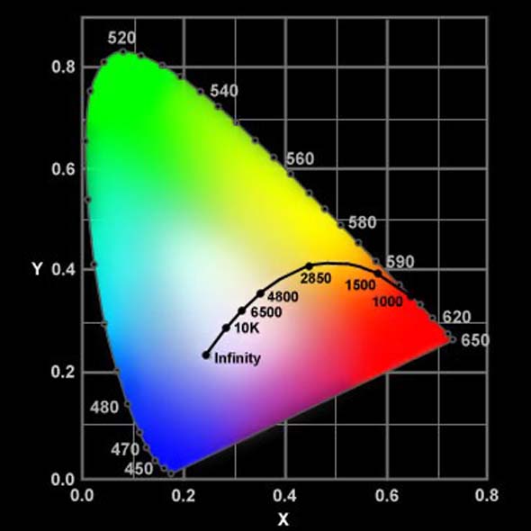
Image 2: Planckian locus in the CIE x,y chromaticity space
Color temperature is usually expressed in Kelvins (K). The Kelvin scale is a measure for absolute temperature (0°C = -273K). Color temperatures over 5000K are defined as cool colors, with hues of bluish white, where lower color temperatures (2700K – 3000K) are defined as warm colors, with hues of yellow and red. Most natural light sources (e.g. sun, stars) very closely follow the Planckian locus. When sources are to be described, which do not emit light exactly matching the black-body radiator, the term Correlated Color Temperature is used. According to ISO/CIE 10526: 1991 (E) a correlated color temperature, Tcp is defined as “The temperature of the Planckian radiator whose perceived color most closely resembles that of a given stimulus at the same brightness and under specified viewing conditions.” [1] [2] [8] [13] [12]
Color and color temperature are not unique parameters to describe a light source. Two light sources with the same chromaticity coordinates xy and color temperature might have a different spectral characteristic and therefore, create different color impressions. Thus, the most accurate way of characterizing a light source or an illuminant is by their spectral power distribution curve (short: SPD curve). [1] [2] [8] [6] [10] [12] [13]
The curve shows the radiant flux emitted by the light source at various wavelengths across the visible spectrum (amount of energy [E(λ)]). Mathematically the spectral power is written as shown in Figure 2.

Formula 1:
Calculation of spectral power
Where
E (λ) is the spectral power/energy,
Φ is the radiant flux,
A is the area over which the radiant flux is integrated and
λ is the wavelength.
Quite often, the relative spectral power is indicated by the ratio of the spectral power at a given wavelength [E(λ)] to the spectral power of a reference wavelength [E λ0].

Formula 2:
Calculation of relative spectral power
Therefore, the SPD curve is normalized (see Formula 3) at the wavelength of 560nm so that the assessment is independent of the absolute level of illumination.

Formula 3:
Mathematical normalization of a spectral power distribution curve
The color rendering index is a quantitative measure of a light source and its ability to reveal colors of objects in comparison with an ideal or natural light source. The term CRI is often used on commercially available lighting products. By proper definition, it should be called Ra – the General Color Rendering Index, or Ri – the Special Color Rendering Index, corresponding to the number of test-color samples that are evaluated.
The CRI is calculated by comparing the color rendering of the test source to that of a defined source. For test sources with a CCT under 5000K a black body radiator is used as the defined source. For test sources above 5000K daylight (D illuminants) are used. The detailed calculation of Ri and Ra is explained in the technical report of CIE 13.3-1995. [4] The test method is using a set of eight (Ra) or fourteen (Ri) CIE-1974 test-color samples from an early edition of the Munsell Atlas. The first eight samples are moderate in saturation, cover the hue circle and are approximately the same in brightness. The other six samples provide supplementary information about the color rendering properties of the light source.
CIE publication 51.2 describes a method to rate the quality of daylight sources. For the visible range the method uses five theoretical sample pairs, where each pair consists of the standard and metameric sample with a MIVIS = 0 for standard illuminant D65. The higher the mismatch between the MIVIS of standard illuminant and MIVIS of the daylight-simulating source, the worse is the quality of the light source. [5] [13] [12]
Pursuant to MIVIS for the visible range, the CIE also defined MIUV for the fluorescent range, with three theoretical metameric sample pairs. The formulas for MIVIS and MIUV are as followed.

Formula 4:
Calculation of the metamerism indices MIVIS and MIUV
Where ΔEi and ΔEj are the L*a*b* (L*u*v*) color differences between the ith and jth pair of metamers.
The classification of MIVIS and MIUV is done according to the following table.
| Category | CIELAB | CIEUV |
|---|---|---|
| A | < 0,25 | < 0,32 |
| B | 0,25 to 0,5 | 0,32 to 0,65 |
| C | 0,5 to 1,0 | 0,65 to 1,3 |
| D | 1,0 to 2,0 | 1,3 to 2,6 |
| E | > 2,0 | > 2,6 |
As there are no actual D65 light sources available, the challenge is to develop a D65 simulator as close as possible to the CIE D65 illuminant. The quality of a simulator is objectively assessed with the CIE Metamerism Index MIVIS, corresponding to quality classes A to E with class A being the most accurate simulation.
Light is electromagnetic radiation within a certain portion of the electromagnetic spectrum. The word light usually refers to radiation that is visible to the human eye (wavelength: 400nm to 700nm). In order to characterize light emitted by a light source several terms are used: color temperature (CT) and correlated color temperature (CCT), color rendering index (CRI Ra) as well as spectral power distribution (SPD) and metamerism index MIVIS.
When speaking about light sources and illuminants it is important to know what the difference between these two terms is. A simple and proper explanation comes from “Billmeyer and Saltzmann”, where a light source is explained as “Physically realizable light, whose spectral power distribution can be experimentally determined”. An illuminant is defined as a “Light defined by a relative spectral power distribution that may or may not be physically realizable as a source.”
The CIE (Commission Internationale de l’Éclairage) defined a number of SPD curves to provide reference spectra for colorimetric applications, the so-called CIE standard illuminants.
Standard illuminant A was introduced by the CIE in 1931 and represents an incandescent tungsten filament lamp. Its relative SPD is that of a Planckian radiator at an approximate temperature of 2856K. To simulate standard illuminant A in a light booth conventional light bulbs or nowadays quartz tungsten halogen lamps (CT≈3000K) are used.

Figure 2:
CIE standard illuminant A and its simulation with tungsten halogen lamps in byko-spectra pro
CIE defined 12 fluorescent lamp types, named F1 to F12, classified into three groups. They differ in the bandwidth and wavelength peak of their emission spikes. Consequently, different color rendering indices and color temperatures are achieved.
| Classified Groups | Lamp Types | Color Temperature Tc | CRI Ra |
|---|---|---|---|
| Standard group | F1 – F6 | 2500 – 7000 K | 60 - 80 |
| Broad band group | F7 – F9 | 2500 – 7000 K | ≈ 80 |
| Three narrow band group | F10 – F12 | 2500 – 7000 K | 80 - 95 |
Among these twelve, F2 and F11 are most commonly used in the industry. F2, also named “CWF” (cool white fluorescent) has a CT of about 4000K and a CRI Ra ≈ 60. F11, also known under TL84, has a CT of about 4000K and a CRI Ra > 85. To simulate standard illuminant F series in a light booth, commercially available fluorescent tubes are used. [11] [16] [17]

Figure 3:
CIE illuminants F2 and F11 and their simulation with fluorescent tubes in byko-spectra pro
In 1964 CIE defined a series of daylight illuminants by numerous measurements of real daylight (see Table 3). Out of 622 measurements, the theoretical SPD curves of daylight from 330nm until 700nm were constructed. CIE standard illuminant D65 is the most important representation of an average daylight at 6504K corresponding to a midday light in Western/Northern Europe, comprising both direct sunlight and the light diffused by a clear sky including UV component.
| Illuminant | Color Temperature [K] | Common Name |
|---|---|---|
| D50 | 5003 | Warm daylight at sunrise or sunset |
| D55 | 5504 | Mid-morning or mid-afternoon daylight |
| D65 | 6504 | Noon daylight |
| D75 | 7500 | Overcast daylight |
In order to simulate daylight, different types of light sources are used in commercially available light booths/luminaires for visual appraisals. Depending on how good the match between artificial light source and standard illuminant CIE D65 is, a sample pair can look very different. In the following example, a sample pair is evaluated in light booth 1 with fluorescent tubes with a CT of about 6500K and a CRI Ra of about 96. The daylight simulation is an approximation of the CIE defined D65 with CIE MIVIS (see Chapter 3.4) Class B quality level (see Figure 4). The difference between this sample pair is very significant under these evaluation conditions.

Figure 4:
Daylight simulation with fluorescent tube
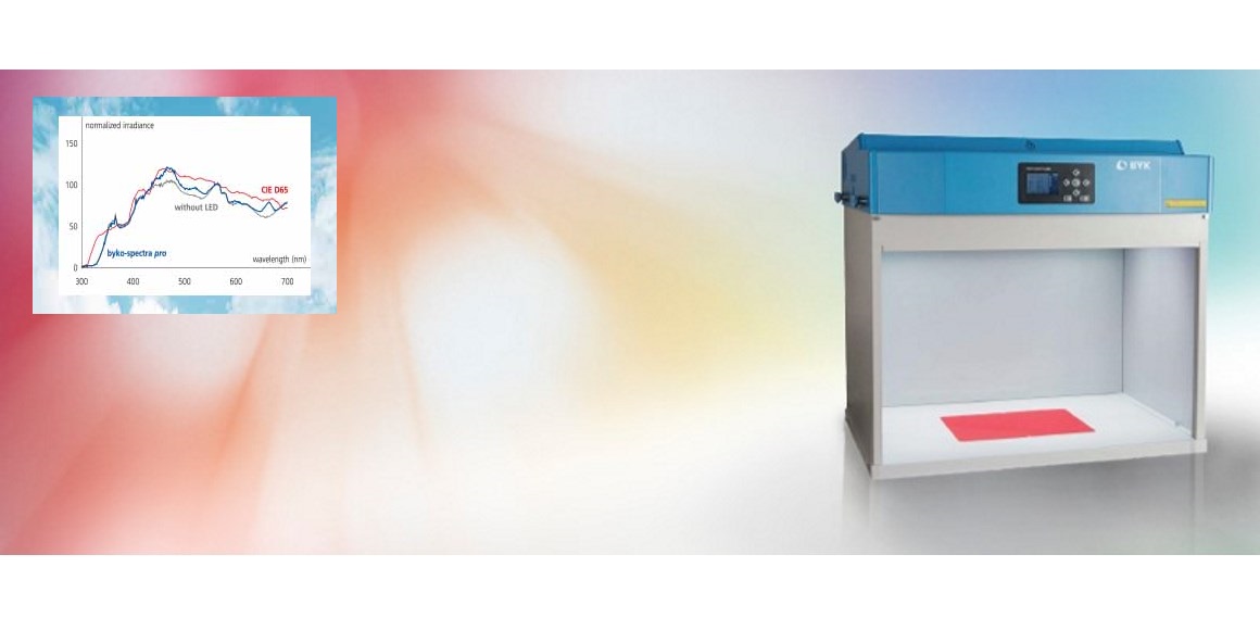
Next, the sample pair is evaluated in light booth 2, byko-spectra pro, using halogen lamps with a specially developed blue filter glass combined with an LED array. This combination creates an excellent simulation of CIE D65 without any spikes (see blue curve in Figure 5) resulting in a CIE MIVIS quality class A. Under theses condition our sample pair will show only a small difference like under natural daylight.

Figure 5:
Daylight simulation with combination of filtered halogen lamps with and without LEDs
BYK-Gardner’s new light booth byko-spectra pro masters the challenge of bringing true daylight into the lab by a smart combination of filtered halogen lamps and LED array. This combination guarantees best in class daylight simulation – tested according to CIE.
Additionally, the built-in sensors in the light booth permanently control the lamp performance and automatically adjust the voltage to guarantee lamp stability. In order to control the lamp condition and trigger lamp replacement actual color temperature, light intensity and lamp operation time are shown on the display of the light booth. To reduce maintenance interval, the class A daylight lifetime is extended to 600 hours.
Depending on a product‘s usage, color needs to match under a variety of illuminations. To be prepared for metamerism the light booth byko-spectra pro offers two daylights illuminants with class A performance (D65 and D75), incandescent lighting (A), three fluorescent illuminants (CWF, TL84, U30) and a UV light for evaluation of fluorescent samples.
As diffused light is essential in the evaluation of solid colors, diffuser panels mix the light to ensure uniform lighting over the entire inspection field. To comply with international standards, the interior walls are painted with a matte light grey color to eliminate influence of the sorrounding on the observer.
Technical performance is not the only key criteria for a light booth. Efficient and comfortable operation also play an important rule for the user. The large color display not only allows the switching of illuminants, but also enables an easy menu guided operation. The included remote control allows switching illuminants from a distance of up to 10 m. An Auto Sequence Mode progresses automatically through the user-defined sequence of illuminants for hands free operation.

Figure 6:
byko-spectra pro light booth
The byko-spectra pro is available as a regular light booth and as luminaires. The luminaires can be hung from the ceiling as a set or as multiple units to outfit an entire color harmony room to evaluate system components or complete products, e.g. car bodies. Luminaires also have the same class A illumination specifications as the light booth, ensuring the needed precision in visual color appraisals.

Figure 7:
byko-spectra pro luminaire
More information is available from BYK-Gardner GmbH, P.O. Box 970, 82534 Geretsried, Germany: By fax: +49 8171 3493-140, the free service no. 0 800 gardner (0 800 4273637) or on the Internet at www.byk-instruments.com.
Author
Tinka Zavcer
BYK-Gardner GmbH, June 2019
Standards
Literature


